Luckily my sister left a stereo in my parents' garage after upgrading her car.
It's a nice little unit.


Now, I'm a crazy person. I like soldering, so I decided to solder all the connections. That's 13 wires and 26 solder points. I also heat shrink wrapped each of them using a lighter. I've heard people complain about this, but keep in mind I just soldered 13 wires.


Once I had the harness completed, I needed to focus on the radio. The only major issue with it is the rear auxiliary input is Sony's proprietary BUS AUX IN. This only turns on when the head unit gets the correct signal from another Sony product through the BUS control connection. I wasn't about to shell out $100 for Sony's BUSlink adapter, which meant I either had to plug into the front of the head unit or make my own adaptations. I chose to adapt. This way I could remove the faceplate or use the front auxiliary input.
So I opened the head unit and took apart the faceplate. This was useless.
I lost a spring. I spent 15 minutes looking on the carpet (which is the exact goddamned gray as the spring). Incidentally, I have some great tricks for finding things in such situations (like taking off your shoes and walking around, a.k.a. finding by feel).

In the picture to the left you can see pins labeled Aux G, Aux L, and Aux R. These pins attach to the cable for the front faceplate.
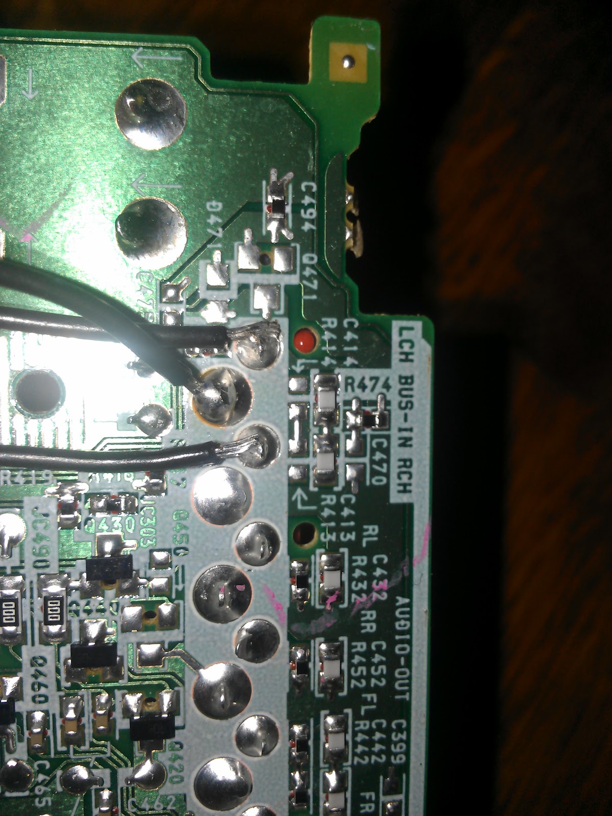
The pins going to the BUS AUX input at the rear of the stereo are fairly obvious. LCH is the left channel. RCH is the right channel. Ground is the big blob in the center.
NOTE: If you don't know what you're looking at in the picture on the right, then you shouldn't try to solder to it... unless you're making abstract art or unique paperweights.

Trusting in Sony engineering, I soldered in some jumper wires and prayed it wouldn't fry something. I reassembled the radio and ran out to the car to plug it in. With my cellphone for sound I tested it and voilà! It worked!
That looks like a lot of work! But it does get easier if you know exactly what you want the computer to do and how you can make it like that. Have you encountered any problems after installing the carputer?
ReplyDelete@Andre Brennan